
HFC Meaning: Hybrid Fiber-Coaxial Networks Explained
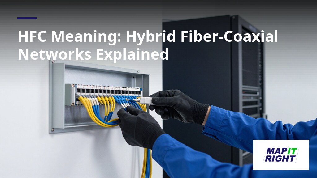
In an HFC system, signals travel from the headend, the distribution facility, to local communities over optical fiber.
HFC stands for hybrid fiber-coaxial, a broadband telecommunications network that combines optical fiber and coaxial cable. Cable television operators have commonly used it worldwide since the early 1990s. In this design, television channels travel from the headend, the cable system's distribution facility, to local communities over optical fiber lines. At each local community, an optical node converts the light signal into radio frequency (RF) and sends it over coaxial cable to subscriber homes and businesses.
The next thing to understand is how the two media divide the work. Fiber carries signals over long distances with high capacity, while the last stretch to the subscriber relies on coaxial cable. The sections below explain the main components of an HFC network, how data is transported through it, and how it compares with other network technologies.
Key takeaways
- HFC stands for hybrid fiber-coaxial, a broadband network that combines optical fiber for long distances with coaxial cable for the final connection to customers.
- Operators use the HFC design because fiber handles trunk and feeder traffic well while existing coaxial cable reduces the cost of reaching the last segment.
- The optical node is the boundary where fiber ends and coaxial cable begins, converting light signals into radio frequency signals for distribution.
- Deciding how many homes a single optical node should serve is a key planning choice that affects bandwidth shared per customer and fiber requirements.
- Verify HFC node details against your own engineering records or a trusted technical standard rather than relying solely on general public reference material.
What Is the HFC Meaning in Telecom Networks?
HFC stands for hybrid fiber-coaxial, a broadband telecommunications network that combines optical fiber and coaxial cable in a single system (Interference detection and avoidance in a telecommunication ). In plain terms, the term describes a network where fiber carries signals over long distances and coax carries them the final stretch to the subscriber. Operators use this design to deliver television, data and voice services over one shared infrastructure.
Hybrid fiber-coaxial defined as a broadband access network
An HFC network is a broadband access network built from two transmission media. Optical fiber forms the backbone and feeder portions, while coaxial cable reaches the homes and buildings. Signals are converted between light and radio frequency at the boundary points, which is what makes the two media work as one network. The HFC network description on Wikipedia summarizes this architecture for readers new to the topic.
Whether a network counts as HFC depends on the criteria it meets: fiber must reach an intermediate point, and coax must complete the connection to the premises. A network that is fiber all the way to the home, for example, is generally classed as fiber-to-the-premises rather than HFC.
Why operators combine optical fiber with coaxial cable
Operators combine the two media because each handles a different part of the problem well. Fiber offers high bandwidth and low signal loss over distance, so it suits the trunk and feeder routes. Coaxial cable is already installed in many buildings, which lowers the cost of reaching the last segment.
- Fiber carries the trunk and feeder traffic over long runs.
- Coaxial cable reaches the premises through existing drops.
- Amplifiers on the coax segment are reduced when fiber shortens the cascade.
- Supported services include video, voice and data on one plant.
- Upgrades can proceed segment by segment without replacing the whole network.
- Two-way traffic becomes practical because fewer amplifiers sit in the path.
Planners need to understand how the hybrid fiber-coaxial design affects where equipment sits and how the network grows.
Who should apply the HFC approach
The HFC design suits operators with a large installed base of coaxial plant who want faster backbone capacity without rebuilding every drop. If you are a smaller operator starting from scratch, building fiber closer to the premises may be simpler. The right answer depends on how much coax already exists and how quickly your network must add capacity.
How Does an HFC Network Work in Practice, Step by Step?
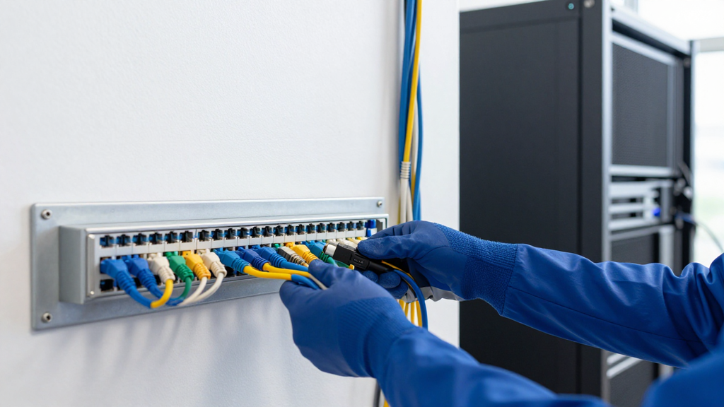
An HFC network works by carrying signals over optical fiber for the long part of the route and over coaxial cable for the final connection that reaches the customer. The fiber carries the signal from the headend toward the neighborhood, and the coaxial segment distributes it from the local node to homes. Each segment handles the job it does best, which is why HFC networks are usually explained as a division of roles rather than a single medium.
What the optical fiber segment carries in an HFC network
The fiber segment begins at the headend, which houses the equipment that processes and distributes signals. From there, optical fiber lines extend to neighborhood nodes. Fiber suits this stretch because it is designed for long-distance transmission and high bandwidth, so the signal can travel a considerable distance before it needs to reach a local area. Operators typically place the fiber in the portion of the network where distance and capacity matter most.
The optical node sits at the boundary between the two media. It converts the light signal arriving on the fiber into radio frequency (RF) signals that can travel over coaxial cable. This conversion is the step that makes the hybrid design work, and it is the point where a planner must decide how many homes a single node should serve.
What the coaxial cable segment delivers to homes
Coaxial cable takes over after the node and distributes services to individual homes, businesses, or multi-dwelling units. It is well suited to short runs and can carry several services at once, including television, broadband internet, and voice. Customer premises equipment, such as a cable modem or set-top box, connects to this coaxial drop to receive those services.
The choice between fiber and coax depends on the distance and the number of customers involved. For a dense cluster of homes close to a node, coaxial distribution is usually the practical option. If you stretch coax over a long distance, however, signal quality can drop, which is why the fiber segment is extended toward the edge of the service area.
A step-by-step signal path from fiber to home
- The headend processes the television channels and data for distribution.
- Optical fiber carries the light signal from the headend to the neighborhood hub.
- The optical node converts the light signal into RF signals.
- Coaxial cable distributes the RF signals to nearby homes.
- Customer premises equipment receives the services and passes them to the devices in the home.
When the design works, a subscriber receives television, internet, and voice from the same physical connection. Planning teams often keep these stages in a single record so they can see where each segment begins and ends. HFC meaning in internet explains the same division in simpler terms.
Where Do Fiber Optic Nodes Sit in an HFC Network?
In an HFC network, the fiber optic node is the boundary where the optical fiber segment ends and the coaxial segment begins. The HFC architecture runs fiber from the headend to these nodes, and coaxial cable carries the signal from each node to the customer. Understanding where the node sits is the starting point for understanding how HFC is built.
What a fiber optic node does inside an HFC network
The fiber optic node receives the optical signal that has travelled from the headend over fiber, and it converts that light into radio frequency (RF) signals. The optical node translates light signals from the fiber into RF signals that can travel over coaxial cable. This conversion is what allows one network to combine the long-distance strength of fiber with the existing reach of coaxial cable.
How the node links the fiber and coaxial segments
The node connects to the headend or hub through fiber in a point-to-point or star topology, and each node can be served by its own dedicated fiber. From the node, a coaxial trunk connects a group of homes in a tree-and-branch layout. Because fiber terminates at the node rather than at each home, the node size and placement shape how many customers share one optical link.
Practitioners generally choose node placement by weighing the number of homes served against the capacity they need to share. A node that serves a small group leaves each customer with more bandwidth, while a node that serves a large group reduces the number of fibers required. If your route has few fibers, wavelength division multiplexing can combine several optical signals on one strand, so the right choice depends on fiber availability as much as on demand.
Documentation and the reliability of node information
HFC network descriptions are widely available, and the general principles are consistent across sources: fiber carries signals over long distances from the headend, an optical node converts the light to radio frequency, and coaxial cable delivers the signal to homes and businesses. The article itself covers how these components divide the work, so readers have what they need to understand the core design. Node details such as how many homes one node serves can vary by operator, and the planning figures that matter most depend on the specific network, so treat any numbers as illustrative and check them against the operator's own engineering data when it comes to real deployment decisions.
Teams that track node locations, fiber routes and coaxial trunks in one place can keep these relationships visible as the network changes. Hybrid Fiber-Coaxial (HFC) Explained for Engineers covers the engineering side of this layout in more depth.
How Does the Final Drop Connect HFC Service to Homes?
In an HFC network, the final connection to a customer runs over coaxial cable, which carries the signal from the neighborhood node to the premises. Fiber handles the long leg from the headend, while the coaxial portion covers the last segment that reaches the home or business. Understanding this last segment helps teams see where service is delivered and where equipment and records need to be kept accurate.
How the drop cable reaches a customer's building
Where a fiber optic cable ends in an HFC node, the optical signal is converted into a radio frequency (RF) signal and sent over coaxial cable to the subscriber. The coaxial cable that enters a home is a flexible, small drop cable. It connects directly to the cable modem, the set-top box, or other customer premise equipment. Because the drop is the point where a service is handed to the customer, record the physical route and the equipment at each end accurately.
How coaxial cable runs from the node to premises
Between the node and the individual drops, coaxial cable forms a trunk and distribution path. Trunk coaxial cables connect to the optical node and form a backbone to which smaller distribution cables attach. Amplifiers are placed at intervals along the trunk to offset signal loss from cable attenuation and from splitting or tapping the line. Trunk cables also carry AC power, which is supplied to the line for the amplifiers.
A practical consideration is the number of splitters between the distribution tap and the customer. If too many splitters are used, the signal level drops and picture quality on analog channels can suffer. In that case a drop or house amplifier is used to restore the signal. The right approach depends on how many outlets share one drop and how far the signal travels, so check levels before you add more splits.
Glossary of key HFC terms
- Node: the point where the optical signal from fiber is converted to RF for coaxial distribution.
- Drop: the small flexible coaxial cable that connects a single premises to the network.
- Headend: the main hub that processes and distributes signals into the network.
- Upstream: traffic sent from the customer back toward the headend.
- Downstream: traffic sent from the headend out toward the customer.
Keeping these terms consistent across field and office records makes it easier to trace a problem from a customer drop back to its node. You can record drop locations and node associations in Hybrid Fiber-Coaxial (HFC) Explained for Engineers style documentation, linking each drop to its trunk and node.
How Does Data Travel Across Fiber and Coax Links in HFC?
Data moves through an HFC network as a signal that changes form at a defined boundary. Light carries it over fiber from the headend toward the neighborhood, and the signal is then converted to radio frequency so it can travel over coaxial cable to subscriber premises. Understanding that handoff is the key to understanding how capacity and traffic direction are managed in the network.
How data moves across fiber and coaxial links
The transport path begins at the headend, where content and data are prepared for distribution. From there, fiber optic cable carries the signal across the backbone toward neighborhood nodes. At each node, an optical node translates the light signal into radio frequency, and coaxial cable takes over for the final distribution to homes and businesses. Because the fiber segment is shared by everything upstream of the node, the design of the fiber path determines how much traffic reaches each service group.
The coaxial segment is a tree-and-branch structure fed from the node. Signals fan out to a group of subscribers, and the number of homes connected to one node shapes how bandwidth is shared. For operators planning an HFC deployment, the criteria to check are the fiber capacity feeding each node, the number of homes on the coaxial trunk, and how many amplifiers sit in the cascade between them.
How downstream and upstream signal paths differ
Traffic in an HFC network runs in two directions. Downstream signals carry content from the headend out to subscribers, while upstream signals carry requests and data back toward the headend. Operators typically assign these directions to different frequency bands and, on the fiber side, to different wavelengths, so both can share the same physical infrastructure without interfering with each other.
The upstream path is the more sensitive one. Because it is shared among many subscribers on the same node, noise picked up along the coaxial segment can accumulate and degrade the return signal. This is why the quality of the node and the condition of the coaxial plant matter so much for the return path. A network with a clean downstream can still show upstream problems if its return path is poorly maintained, so evaluate both directions separately.
Keeping accurate records of nodes, cable routes, and amplifier locations lets you trace a degraded path much faster. MapItRight offers GIS overlays for comprehensive viewing, which lets field and office staff see the fiber and coaxial segments on the same map when they investigate a path.
| Element | Downstream path | Upstream path | Key check |
|---|---|---|---|
| Direction of traffic | Headend to subscriber | Subscriber to headend | Confirm which band each direction uses |
| Fiber role | Carries signal to the node | Carries return signal back to the headend | Verify wavelength plan on each fiber |
| Coaxial role | Distributes signal to homes | Collects return traffic from homes | Inspect cable and amplifier condition |
| Sensitivity | Generally more stable | Sensitive to accumulated noise | Review the return path separately |
The exception that changes practice is a node with a heavily loaded return path. In that case, splitting the node into smaller service groups can relieve congestion, but it requires additional fiber and optical equipment. Whether that investment is justified depends on how much upstream traffic each group carries. For a deeper look at the broader architecture, see Hybrid Fiber Coaxial Networks: The Backbone of Modern Connectivity.
How Did HFC Networks Evolve from Earlier Cable Systems?
The HFC network evolved as cable operators moved optical fiber closer to customers while keeping coaxial cable for the final connection. The reason is practical: coaxial cable carries signals well over short distances but degrades over long runs, so each generation of design pushed fiber further out and reduced the amount of coaxial plant between the headend and the home.
How HFC networks developed from early cable television plant
Early cable television systems relied almost entirely on coaxial cable. Signals travelled from the headend through long cascades of amplifiers, and each amplifier added noise and distortion. Cable operators reduced the number of amplifiers in cascade on the coaxial parts of the network, and hubs were introduced to improve signal quality as the network expanded. Supertrunks linking the headend to hubs were first built with coaxial cable, then with microwave links and fiber optics. Fiber was first used as a supertrunk in the 1970s, which marked the start of the hybrid design.
When comparing generations of network design, the useful method is to track where the fiber ends and how many coaxial amplifiers remain in the signal path. A plant with fiber running only to a hub still carries a long coaxial cascade, while a plant with fiber reaching a node close to the subscriber carries far less. Operators who want to judge how far a legacy network has evolved should check exactly this boundary rather than relying on the network's age.
Why operators moved fiber closer to customer premises
Moving fiber closer to customers improves the signal, because the optical link carries the signal over distance with little loss and the coaxial section that remains is short. In a typical design, fiber runs from the hub to a node that serves a bounded group of homes, and the node converts the optical signal to radio frequency for the coaxial drop. Fewer amplifiers in the coaxial path means fewer points where noise accumulates, which is the main reason the design shift matters for operators.
The trade-off depends on the length of your existing coaxial plant. If the coaxial runs are already short, moving the node closer yields little benefit, and the cost of new fiber may not be justified. Where the coaxial cascade is long and degrading service, pushing fiber outward is usually the more effective upgrade.
How Can Teams Map and Track HFC Network Assets With MapItRight?
HFC networks are commonly run by cable television operators, and the people who manage them are usually organized around the systems they operate. Mapping those assets accurately means knowing which operator owns which part of the plant, where the fiber and coaxial segments meet, and who is responsible for each segment. The clearer that record is, the easier it becomes to plan changes and respond to faults.
What multiple-system operators manage in HFC networks
A multiple-system operator, often shortened to MSO, is a company that owns and runs several separate cable systems rather than a single one. In an HFC context, an operator of this type typically oversees a headend or hub, the fiber backbone feeding its nodes, and the coaxial plant serving subscriber areas. Each of these layers can be operated by different teams, which is why a single shared map becomes important as the network grows.
The criteria that define an operator type are mainly scale and structure. A small operator may run one headend serving a single town, while a multiple-system operator spreads its responsibility across many headends and service areas. The mapping approach should match that structure: a team managing one system can work from a simple plant view, whereas a team responsible for several systems needs to separate records by system and by segment so that changes in one area do not blur into another.
Which cable television operators rely on HFC plant
Cable television operators are the main group that relies on HFC plant, because the architecture was built to carry television channels from a distribution facility out to local communities over optical fiber and then over coaxial lines. Operators that also deliver internet access and voice services over the same plant rely on the same asset records for maintenance, expansion and customer activation.
It depends on how your operator's services are structured. An operator that offers only television over its HFC plant tends to track fewer active devices than one that also runs broadband and voice on shared segments. In the second case, a fault on a single node can affect several services at once, so asset records need to show which services depend on which segment before a repair is scheduled. You can use MapItRight to keep GIS overlays and plant records in one place, which helps you see those dependencies at a glance.
How Does HFC Compare With Other Broadband Access Technologies?
HFC, or Hybrid Fiber-Coaxial, is a broadband network architecture that combines optical fiber and coaxial cable to deliver services to subscribers. A comparison with other broadband access approaches is most useful when it looks at three neutral criteria: the transmission medium, the path the signal takes to the customer, and how the network is structured. Judged on those criteria, HFC sits between fiber-only designs and older all-copper or all-coaxial designs, which is why the comparison depends on what the operator is trying to upgrade or extend.
How HFC differs from fiber-only network designs
The clearest difference lies in the last segment of the network. In an HFC design, fiber runs from the headend to a fiber optic node, which converts the optical signal into a radio frequency signal and sends it over coaxial cable to subscriber premises. In a fiber-only design, fiber continues all the way to the customer, so no conversion to RF and no coaxial drop is needed. HFC therefore reuses existing coaxial plant in the last mile, while fiber-only designs replace it entirely.
The method for making this comparison is to follow the signal from the headend to the home and note where the medium changes. Each change is a point where the architecture, equipment and maintenance responsibilities differ. For example, when comparing an upgrade path, ask whether the coaxial drop will remain in service or be retired. If it remains, an HFC approach may be the practical choice; if the plant is being rebuilt anyway, a fiber-only design may be simpler to operate over time.
Where HFC fits among other broadband access options
HFC sits in the middle of the broadband access spectrum. It keeps the long-distance and trunk capacity of fiber while reusing coaxial lines for the final connection, so it is a common choice for operators that already own a coaxial network. Shared bandwidth within a service group is a structural trait of HFC that teams should account for when comparing it with designs where each customer has a dedicated fiber path.
The decision depends on your existing plant and your goals. Where coaxial infrastructure is already in place and your priority is extending high-capacity transport closer to subscribers, HFC is a logical step. Where you are building the network from scratch or the existing coaxial plant is at the end of its useful life, a fiber-only design may be the better fit.
How Can Field and Office Teams Organize HFC Network Records With MapItRight?
HFC network records stay useful only when the people who build the network and the people who manage it are looking at the same information. Field crews need to see where cable runs, which nodes serve which areas, and what has changed since the last survey. Office staff need the same picture to plan upgrades, answer customer questions and track assets. MapItRight supports this shared view through GIS overlays, real-time collaboration and an intuitive interface, so records are kept in one place rather than split across spreadsheets and drawings.
Layering HFC network records on a map view
An HFC network combines fiber trunks, nodes and coaxial distribution, and each layer answers a different question. A map view works well when records are organized as separate layers that can be turned on and off. For example, a team reviewing a neighborhood can display the fiber routes and nodes first, then add the coaxial plant only when it needs to check drops and taps. This keeps the screen readable and prevents a single crowded drawing from hiding the detail that matters for the task at hand.
MapItRight's GIS overlays for comprehensive viewing let teams place HFC records on a map in this layered way. The choice of which layers to show depends on the job. A maintenance crew checking a fault needs the physical route and nearby equipment, while a planning team comparing service areas needs boundaries and capacity summaries. Deciding which layers belong on each view before records are entered saves rework later.
Sharing HFC records between field and office teams
Records lose value when a field change takes days to reach the office, or when an office update never reaches the crew that needs it. Real-time collaboration reduces that gap, because the people editing the network and the people reviewing it work from the same current data. A technician who confirms a new drop can record it while still on site, and an engineer at the office sees the change without waiting for a separate report.
Shared access needs clear rules. Agree on who may edit each layer and who only reviews it, so that field notes do not overwrite engineering decisions by accident. MapItRight's intuitive interface helps less technical staff use the shared view, but the ownership rules still have to be set by your team. The right balance depends on team size: a small operator may let most users edit everything, while a larger one usually separates field entry from office approval.
Frequently asked questions
Is HFC the same thing as fiber-to-the-home?
No, HFC and fiber-to-the-home are different architectures. An HFC network runs optical fiber from the headend to a node, then converts the light to radio frequency and uses coaxial cable for the final stretch to the premises. In a fiber-to-the-home design, fiber continues all the way to the customer, so no conversion and no coaxial drop are needed. Planners comparing the two should start by checking where the conversion point sits in each design. For a deeper engineering view, see Hybrid Fiber-Coaxial (HFC) Explained for Engineers.
Does an HFC network use only coaxial cable?
No, an HFC network uses both optical fiber and coaxial cable. Fiber carries the signal over the long part of the route from the headend to each node, and coaxial cable carries it from the node to the subscriber. Coax alone would not reach the backbone capacity the fiber segment provides. A practical check is to trace a route on a map and confirm that a fiber segment ends at a node before the coaxial plant begins.
What do the terms node and drop mean on an HFC network?
The node is the point where the optical signal from the fiber is converted into an RF signal for coaxial distribution. The drop is the final coaxial cable that runs from the neighborhood plant to an individual building. When you review records, trace each drop back to its trunk and to a specific node. Keeping those associations current is easier when the records sit on a shared map; the HFC definition in the MapItRight glossary summarizes the terms.
How can I check whether an HFC explanation is reliable?
Check whether the explanation names the fiber segment, the node, and the coaxial segment, and whether it describes the signal conversion at the node. A reliable source will also distinguish HFC from fiber-only designs rather than treating the two as interchangeable. Be cautious with general reference material that is open to editing, and compare it against engineering documentation. Comparing several sources, including Understanding Hybrid Fiber Coax: The Future of Connectivity , helps you confirm the core facts.
Conclusion
HFC, or hybrid fiber-coaxial, is a broadband telecommunications network that combines optical fiber and coaxial cable. Fiber carries the signal over the long part of the route to a fiber optic node, where it is converted to radio frequency and sent over coaxial cable to the subscriber, a design cable operators have commonly used since the early 1990s.
For teams that manage HFC records, the practical next steps are to confirm where each fiber optic node sits and which coaxial trunk it feeds, to record the final drops against their nodes, and to review the upstream return path separately from the downstream path, since return traffic is more sensitive to accumulated noise. Keeping these records current makes later upgrade and maintenance decisions easier to verify.
MapItRight offers GIS overlays for comprehensive viewing, which lets field and office staff place fiber segments, nodes and coaxial distribution on the same map.