
Exploring HFC Spectrum: Understanding Its Role in 2026
Learn how the HFC spectrum carries TV, broadband and voice over hybrid fiber-coaxial plant, from headend and optical nodes to the coaxial drop.
In practical terms, the HFC spectrum refers to the band of radio frequencies used on the coaxial portion of a hybrid fiber-coaxial system, where television, broadband internet, and voice services are carried to subscribers. The underlying architecture pairs optical fiber with coaxial cable, a combination that cable television operators have widely used since the early 1990s.
In that architecture, signals travel from the headend to neighborhood nodes over fiber, where an optical node converts them to radio frequency for distribution over coaxial lines to homes and businesses. Understanding how the spectrum is divided and used is essential for planning capacity and mapping the plant in 2026. The sections that follow explain the network components, the spectrum's role, and how to map and manage the infrastructure.
Key takeaways
- An HFC network splits its work: fiber carries signals over long distances, while coaxial cable distributes them to subscribers in the neighborhood.
- The optical node is the boundary where light signals become radio frequency, so a fault at the node can affect every customer downstream of it.
- Node records should be reviewed on a regular schedule and updated the same day any plant change is made, so engineers do not work from outdated information.
- Most customer-facing issues trace back to the coaxial path between the node and the premises, which makes that segment the first place to check.
What Is an HFC Network and How Does It Combine Fiber and Coaxial Cable?
Each medium handles the part of the path it does best: fiber carries the signal over long distances from the headend, while coaxial cable distributes it to subscribers in the local neighborhood. The spectrum the network uses is only useful once both media are working together, so the division of work between them determines how capacity is planned and where faults are likely to appear (Hybrid fiber-coaxial).
Why cable television operators deploy HFC networks
Cable television operators have commonly employed HFC networks since the early 1990s. In this architecture, television channels leave the distribution facility, the headend, and travel to local communities over optical fiber subscriber lines. Operators keep the existing coaxial plant in place where it already reaches homes, which reduces the need to rebuild every last segment in glass.
The choice of architecture depends on the situation. Where a plant already has a long coaxial trunk in good condition, an operator may extend fiber only as far as needed to reach the nodes, leaving the existing coaxial trunk intact. Where the coaxial plant is aging or heavily cascaded, a larger share of fiber is the more practical path, and the planning team has to weigh the cost of each approach against the performance it delivers.
Where optical fiber sits in the HFC network path
Optical fiber runs from the headend out to a neighborhood hubsite and then to an optical-to-coaxial node. At the node, the light signal is converted to radio frequency (RF) and sent onto coaxial cable, which then connects the homes that node serves in a tree-and-branch configuration.
- Headend: the master headend receives video signals and routes IP traffic.
- Fiber trunk: optical fiber carries the signal to regional or neighborhood hubsites.
- Optical node: the light signal is converted to RF.
- Coaxial trunk: RF travels to the homes served by that node.
- Drop to premises: the signal reaches each subscriber.
When a team checks this path, the first question is which segment is fiber and which is coaxial, since each segment has different fault behavior and different maintenance records. Hybrid fiber coaxial explained for engineers covers the engineering detail behind that boundary.
How Does Signal Transport Travel Across an HFC Network?
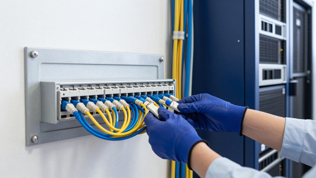
Transport over an HFC network moves a service signal through two different physical media in sequence: optical fiber for the long run from the headend, then coaxial cable for the last stretch into the neighborhood. Each part of that path does a different job. The fiber carries the signal efficiently over distance, and the coaxial plant distributes it to individual premises. Understanding the handoff between the two is what lets a planning team reason about where a signal can degrade and where capacity is available.
How signals travel across the fiber segment of HFC
The transport path begins at the headend, the main hub that processes and combines the signals for distribution. From there, fiber optic cables carry the light-based signal to neighborhood nodes. Because optical transmission supports high bandwidth and long distances, the fiber segment is the efficient backbone of the network. Services such as analog and digital television, video on demand, telephony and internet traffic all ride on radio frequency signals that are multiplexed onto this path.
How signals hand off from fiber plant to coaxial plant
At the neighborhood node, the optical signal is converted into radio frequency signals that can travel over coaxial cable. The node also includes a return-path transmitter that sends customer traffic back toward the headend. This conversion point is where the transport path changes medium, so it is the first place a team checks when signal levels differ between fiber and coax.
- Confirm the signal leaves the headend on the fiber backbone toward the target node.
- Verify the optical node converts the light signal to the downstream RF band used by the hfc spectrum.
- Trace the coaxial trunk from the node outward through its amplifiers and taps.
- Check the return path from customer premises back to the node and headend.
When the handoff is correct, the downstream RF levels at the node match the design values, and return traffic reaches the headend without distortion. Those are the checkpoints to confirm after any change to the node or the coaxial trunk.
| Segment | Medium | Primary role | Typical check |
|---|---|---|---|
| Headend to node | Optical fiber | Long-distance backbone | Optical signal integrity |
| Optical node | Conversion point | Light to RF handoff | Downstream RF level |
| Node to premises | Coaxial cable | Last-mile distribution | Amplifier cascade and levels |
| Premises to headend | Coax and return path | Upstream traffic | Return-path noise |
The exception is a plant with a long coaxial cascade, where transport quality depends more on amplifier count than on the fiber segment, so the coax checks deserve the most attention. Teams that map these segments in HFC meaning and network structure can see where the HFC spectrum is actually used.
What Role Do Fiber Optic Nodes Play in an HFC Network?
In a hybrid fiber-coaxial (HFC) network, the fiber optic node is the point where the optical portion of the plant ends and the coaxial portion begins. Light signals arriving over fiber are converted into radio frequency (RF) signals that can travel over coax to the homes and businesses served by that node. Every downstream and upstream path in the outside plant passes through this conversion, which makes the node the most important boundary to understand when planning or troubleshooting an HFC network.
Fiber optic nodes as the boundary between fiber and coax
The fiber side of the node carries light over long distances, usually from a headend or hub toward a neighborhood. Fiber cables connect the headend or hub to the optical nodes in a point-to-point or star topology, and each node may have its own dedicated fiber. On the coaxial side, the node feeds a tree-and-branch distribution plant. Because the conversion happens here, a problem at the node can affect every customer downstream of it, while a problem past the node usually affects a smaller group of subscribers.
How node location shapes the coaxial plant it serves
Where a node sits determines how much coaxial plant sits behind it and how many premises share that plant. A node that is placed close to the customers it serves generally leaves a shorter coaxial run, while a node placed farther out can extend the coax trunk and branches. Teams therefore use node placement as a planning decision: a neighborhood with many premises per block may justify a node sized for that density, whereas a sparse rural area may need a different split of fiber and coax. The right choice depends on the local premises count and the physical route available, not on a fixed rule.
A practical checklist for keeping node records current
Node records are only useful if they stay accurate, so teams should review them on a regular schedule. Start by confirming which fiber strands feed each node, then record which coaxial branches and taps sit behind it. Next, check that the node's location, serving area and downstream plant match what is in the field. When a plant change is made, update the record the same day so the next engineer does not work from outdated information.
For a broader introduction to how these networks are built, read Hybrid Fiber Coaxial Networks . Engineers who want a more technical view can also review HFC explained for engineers.
How Is the Final Connection to Customers Made on HFC Plant?
The final connection to customers is the coaxial segment that carries service from the distribution network to the subscriber location. In an HFC design, the fiber portion ends at the optical node, and everything after that point is coaxial cable, so the last link is where the broadband signal is handed to the home. Understanding this segment helps you locate faults quickly, because most customer-facing issues trace back to the coaxial path between the node and the premises.
Coaxial plant as the last link to the subscriber
After the optical node converts the light signal back to radio frequency, the signal moves onto a coaxial trunk. That trunk feeds a tree-and-branch layout, which fans out from the node toward groups of homes. Each service group shares the same RF channels, so the coaxial plant determines how the bandwidth is divided among the customers it serves. For network planners, this means the plant records for the coax section need to show which branches and taps belong to which service group, along with the HFC spectrum allocated to each one.
A useful way to think about the coaxial last link is as a shared path with branch points. Signal quality at a home depends on the cable length and the number of taps between it and the node. When a team reviews the plant, it checks whether the trunk and branches still match the design records, since changes made in the field can alter the signal path without anyone updating the drawing.
Drop connections from distribution plant to customer premises
The drop is the short coaxial run that connects a tap on the distribution plant to the subscriber's premises. Drops are usually the most numerous and most frequently changed elements of the network, which makes them easy to lose track of. A tap port that serves one home today may serve a different home after a move or a service change, so accurate drop records are essential for dispatching technicians to the correct location.
The practical method is to record each drop against its tap, its service group and its premises. When a fault is reported, the team starts at the premises and works back toward the tap, checking whether the problem is isolated to one drop or affects the whole branch. A single failing drop points to a connector or cable issue at the home, while several drops failing on the same branch suggests a fault further upstream.
How Have HFC Networks Evolved From Early Cable Plant to Today?
HFC, or hybrid fiber-coax, networks have changed their design over time, and the shift is best understood as a sequence of plant upgrades rather than a single event. Cable operators commonly adopted this design from the early 1990s onward, moving fiber closer to subscribers while keeping much of the existing coaxial plant. The evolution explains why today's plant looks the way it does, and why hfc spectrum planning changes as the network is rebuilt.
How early cable plant became today's HFC networks
Early cable television systems distributed signals over coaxial cable only, with the headend feeding long coaxial trunks and many amplifiers in cascade. In the 1970s, operators began adding hubs to improve signal quality as networks grew, and they worked to reduce the number of amplifiers in cascade on the coaxial parts of the network. Fiber optic supertrunks then connected headends to hubs. Over time this combination produced the hybrid design, in which optical fiber carries signals from the headend to local communities and coaxial cable distributes them to subscribers.
If you run an operator with a coaxial-only plant that wants more channels or two-way service, start by reviewing the cascade depth and amplifier count in each area. The areas with the deepest cascades usually come first in a rebuild, because they limit signal quality the most.
Moving fiber closer to subscribers through successive upgrades
Each upgrade pushes optical fiber further toward subscribers. In a hybrid system, an optical node translates the light signal to radio frequency and sends it over coaxial lines, so moving the node closer to homes shortens the coaxial segment and reduces the number of amplifiers per service group. Reducing the number of subscribers per service group is one common way to improve service, which is why operators often split large groups into smaller ones.
The direction of the upstream path also changes during these upgrades. Early cable networks were largely one-way distribution systems, and two-way service became practical as operators added return-path capability to the plant. Before an upstream change, check the proposed frequency split, because the choice between a mid, high, or ultra-high split affects how much return-path bandwidth is available for upstream traffic. This is the point where spectrum allocation becomes a planning constraint, not just a technical detail.
How Do Multiple-System Operators Manage Their HFC Networks?
A multiple-system operator, usually called an MSO, is a company that runs several separate cable systems at once. In HFC planning, that structure matters because each system has its own headend, node layout and coaxial plant, while the operator still needs one consistent way to record, maintain and report on the spectrum those systems use. The section below explains how the role is defined and how practices are shared across the systems an operator controls.
How multiple-system operators are defined in cable networks
The term describes ownership and management scope rather than a particular technology. An operator becomes an MSO when it holds several franchised or independently run cable systems, each with its own headend and distribution plant. A single HFC network starts at a headend, reaches local communities over fiber, and ends on coaxial cable, so each system carries its own fiber trunk and node topology. Because every system is built from these parts, an MSO has to track the same kinds of assets across many locations.
Responsibility shapes how plant records are kept. An operator running several systems must know which node feeds which coaxial segment, which headend serves which community, and how each system's HFC spectrum is allocated between downstream and upstream traffic. When those records are scattered across separate teams or files, the same question can receive different answers depending on which system is being examined, which is why the definition of the operator's scope drives the maintenance structure.
How one operator's several systems share HFC practices
Shared practice usually means applying one set of rules to every system: the same naming convention for nodes, the same method for documenting amplifier cascades, and the same review cycle for HFC spectrum headroom. Standardizing these methods lets a team compare systems directly and move staff between them without relearning the records. For example, a regional operator might review upstream noise on each system's return path using the same checklist, so that a problem found in one community can be checked quickly in another.
The exception is an operator whose systems differ sharply in age or upgrade status. A legacy system that still runs a long coaxial cascade may need different thresholds and more frequent checks than a system that has already shortened its amplifier chain. In that case the shared method should set common fields and definitions, while the review intervals and limits are adjusted per system.
How Does HFC Compare to Other Access Network Technologies?
HFC, or hybrid fiber-coax, is best compared with other access designs by the criteria a network owner actually applies: reuse of existing plant, the bandwidth available to shared users, the cost of extending service, and how the design scales when demand grows. HFC keeps fiber in the trunk and feeder portions and uses coaxial cable for the final stretch, so the answer to "which is better" depends on which of those criteria matters most for the build being planned. The sections below set out those criteria and show how the fiber-plus-coax design differs from other access approaches.
Criteria for comparing access network technologies side by side
A fair comparison starts with a fixed set of criteria applied the same way to every option. Reuse of existing infrastructure is usually the first test, because an operator with a large coaxial plant has a different starting point from one building new routes. Shared bandwidth is the second test: on an HFC network, bandwidth is shared among the users served by a given node, so capacity planning has to account for how many subscribers sit behind each segment. Cost to extend service and the ability to upgrade without rebuilding the whole plant complete the core set.
When comparing fiber and coaxial designs for a specific HFC plant, teams can make the comparison concrete by setting a threshold for each criterion, such as the number of homes a segment must reach or the hfc spectrum capacity it must carry. Applying the same thresholds to each candidate design keeps the discussion tied to the plant's actual constraints, including node count, cascade depth, and the service mix on each segment.
Where HFC's fiber-plus-coax design differs from other access designs
The defining difference is where fiber stops and coaxial cable begins. In an HFC network, the fiber trunk carries the signal from the headend toward the neighborhood, where an optical node converts it to radio frequency for distribution over coax to homes. Because the coaxial portion already exists in many cable plants, HFC can add capacity in the trunk without replacing every drop. That is why HFC is often chosen when an operator wants to extend a cable footprint rather than start from nothing.
| Criterion | HFC (fiber plus coax) | Full fiber access | Legacy all-coax plant |
|---|---|---|---|
| Reuse of existing coaxial plant | High, final stretch stays on coax | Low, new fiber routes required | High, but limited upgrade path |
| Shared bandwidth per segment | Shared among users on each node | Typically dedicated per premises | Shared, with amplifier cascade limits |
| Upgrade path | Can add capacity in fiber trunk | Upgrades mostly in active equipment | Often requires plant rebuild |
| Best fit | Extending an existing cable footprint | New builds or dense high-demand areas | Maintaining plant that is still in service |
What Does HFC Spectrum Mean for Broadband Service on Coaxial Plant?
In practical terms, the spectrum an HFC network uses on its coaxial portion is what carries broadband service to subscribers. In an HFC network, the fiber carries signals from the headend toward the neighborhood, and at the optical node those signals are converted to radio frequency and sent across coaxial cable to subscriber premises. How that frequency range is divided and planned determines how much capacity each service group can share, which is why it matters so much for broadband planning on coaxial plant.
Frequency bands carried on the coaxial segment of HFC
On the coaxial segment, the usable frequency range is split into bands that carry different traffic. Because the same coaxial cable is used in both directions, the frequency band is divided into two sections so that signals do not interfere with each other. Planners review how the HFC spectrum is allocated across these bands to confirm that television channels, data services and other traffic each have room to operate on the plant.
The exact allocation depends on the regional frequency plan an operator follows. Some countries have traditionally used one band split and others use a different one, so a team working across regions should confirm the plan in force before changing any allocation.
Downstream and upstream spectrum use on HFC coaxial plant
Downstream traffic travels from the node toward subscribers, while upstream traffic travels from subscribers back toward the node. Both directions share the same coaxial path, so the HFC spectrum assigned to each direction directly affects how much return capacity is available for customers. A practical review compares the traffic each service group generates in each direction against the hfc spectrum reserved for it.
Teams typically work through the review in a simple sequence:
- Identify the service groups fed by each optical node.
- Record the frequency blocks assigned to downstream and upstream traffic on each segment.
- Compare current usage with the headroom remaining in each direction.
- Flag segments where upstream headroom is limited and plan a split or a change in allocation.
Upstream headroom is often the constraint that surfaces first, so it deserves close attention during planning. If a segment shows little return capacity, reviewing service group size may matter more than adding downstream capacity.
MapItRight offers GIS overlays for enhanced visualization, which lets teams map frequency allocations against the plant records they already hold and share that view across the team.
How Can Teams Use MapItRight to Visualize and Share HFC Spectrum and Plant Data?
Teams managing a hybrid fiber-coaxial network need a shared picture of how their plant is laid out and how much usable frequency room each segment has. MapItRight offers real-time collaboration and GIS overlays for enhanced visualization, which gives field crews and office planners one place to work from. The method below explains how to organize that work so that HFC spectrum decisions rest on the same plant data everyone can see.
Viewing fiber and coax layers together in map overlays
The first step is to keep the fiber backbone and the coaxial distribution plant on separate but aligned layers. The fiber layer shows the path from the headend to each optical node, while the coax layer shows the distribution tree that the node feeds. Placed on the same map, the two layers make it clear which coax segments depend on which node, and that dependency is what determines how a change in one part of the plant affects the frequency plan downstream.
When you review HFC spectrum headroom, the overlay also helps you see where the plant is nearing its limit. Compare segment boundaries with service areas and flag the parts of the coax plant that serve the most customers. For example, a planner reviewing a neighborhood before a bandwidth change can check both the node location and the coax branches in one view instead of reconciling separate drawings.
Keeping plant records consistent across field and office teams
Records drift when field crews update the plant in the field and office staff work from older drawings. A shared platform with real-time collaboration lets both groups edit the same plant record, so a splice or node change made in the field appears for planners without a separate handoff. Consistent records matter because frequency decisions made from outdated plant data can leave a segment short of usable spectrum.
The exception to watch is a segment that has been partly rebuilt but not fully documented. In that case, teams should mark the segment as under review until both the field update and the office check are complete, rather than planning spectrum changes from a record that may not match the plant. Once the record is confirmed, the segment can be used for planning again.
Using the interface to keep plant information accessible
MapItRight provides an intuitive interface, which lowers the barrier for staff who do not work with mapping tools every day. Technicians can check a segment, and planners can review HFC spectrum allocation on the same map without training on separate systems. Keeping the view simple is part of the method: the goal is to make the plant data easy to read, so that frequency decisions are based on what is actually on the map.
Frequently asked questions
How can I tell from a network diagram whether a segment is fiber or coaxial?
Look at the line style and the labels on the diagram, since fiber segments usually run as long trunks from the headend or hub toward a neighborhood, while coaxial segments fan out from an optical node into branches and taps. A fiber run ends at the node, and everything downstream of that point is coaxial, so the node symbol is the boundary to check first. Confirm the segment type against the plant record before acting on it.
Does adding more fiber closer to subscribers change how the coaxial plant is used?
Yes, it does. When fiber moves closer to subscribers, each optical node serves fewer premises, and the coaxial plant behind it becomes shorter with fewer amplifiers in cascade. That changes how the HFC spectrum is shared among a service group, so you should revisit node boundaries and service group assignments after each upgrade.
What should a small team check first when inheriting an HFC map it did not create?
Start by confirming that the map matches the physical plant, beginning with the headend, the fiber trunks and the optical nodes, because every other record depends on them. Next, trace one or two branches from a node down to several taps and drops, and check that the labels and service group assignments agree with what field crews find. Record any gaps before you change anything, so you know which parts of the map you trust.
How often should HFC plant records be reviewed to stay useful?
Review frequency should follow how often the plant changes, so any segment that has been rebuilt, split, or re-noded deserves a check as soon as the work closes out. A regular scheduled review, paired with a check after each field change, keeps the records aligned with the network. Teams that rely on one shared record set, such as the one described in the HFC Meaning: Hybrid Fiber-Coaxial Networks Explained article, find drift easier to catch.
What is the difference between a service area and a node's served plant?
A service area is the geographic region the operator sells service to, while a node's served plant is the physical set of coaxial branches, taps and drops that a single optical node feeds. The two often overlap but are not identical, since a service area can span several nodes and a node can serve only part of a neighborhood. Keep both records separate so that a capacity question about the node does not get answered with a boundary drawn for marketing.
Conclusion
In practical terms, the range of radio frequencies a hybrid fiber-coaxial network uses to carry television, broadband and voice services over its coaxial portion is what planners manage, once fiber has carried the signal from the headend to the optical node. Planning that band well means understanding how the fiber-to-coax handoff at the node, the coaxial trunk and drops, and the shared service groups fit together, from early cable plant to today's MSO-managed systems.
Next, record each optical node, the service groups it feeds, and the frequency bands assigned on its coaxial segment, using one naming convention across every system. Then review downstream and upstream allocations against current demand on a regular schedule so that return capacity is not overlooked. Finally, keep fiber and coax records aligned so that any change to a node or tap is reflected in the spectrum plan.
MapItRight offers GIS overlays for enhanced visualization and real-time collaboration, so field crews and planners can review node locations and coaxial plant on the same map. MapItRight keeps these records in one shared view as the network changes.